Application of Computer in Apparel Manufacturing
Question Bank (BUTEX)

Download Link
(0)
Application of Computer in Apparel Manufacturing

(0)
(0)
Name of the Experiment: Study on material passage diagram of Breaker Carding Machine
Introduction:
After the fiber from the softening machine has been conditioned for the desired time, it is ready for one of the most important processes in the cycle of jute manufacture: this process is termed carding. In the carding, the operation the long strands of jute are converted into a continuous ribbon of fibers. The ribbon is known as sliver. Different qualities of jute in the batch are also blended and much shorter fibers are removed too. The machines used in the carding process are generally two types-
Breaker Carding:- In different jute mills the carding operations has been carried out in two ways:
The material after piling more than 24 hours is used hand feed breaker where the material after piling for 12 hours used in the roll feed carding. In this machine, softened jute, after pilling, is fed by hand in suitable mass. By action with different rollers, the machine turns out raw jute in the form of jute slivers for finisher carding. Breaker cards are usually half circular and down striking and have two pairs of workers and strippers. In this process, root cutting is necessary before feeding the material to the hand-feed breaker carding machine.
Objectives:
To Split up & Breakdown the jute fiber.
To individualize & parallelize the jute fibers.
To straighten the jute fibers.
To remove trash from jute fibers.
To remove short fibers.
To convert the reeds of jute into a uniform fibrous strand, sliver suitable for further processing.
Input: Emulsified long reeds of jute
Output: Breaker carded sliver
Main Parts:
Working Principle:
Normally 6-8 roll spreader slivers are feed onto the feed sheet from a creel at floor level and material passes up towards the feed rollers of the breaker card.
① The jute now enters the space between the shell and pin feed roller which travels towards the swift moving pins of the main cylinder.
② When the feeding ends of the reeds meet these fast-moving pins, then they are split, opened out and converted into a fibrous beard.
③ After shell feed operation, the jute reeds come into the real carding action carried out by two pairs of workers and strippers.
④The essential features of this worker and stripper action are combing, teasing, spitting as the fiber is transferred from the cylinder to worker, then from the worker to stripper and finally from the stripper back to the cylinder.
⑤ The wastage is then discharged through the tin cylinder.
⑥ In this way, jute fiber passes 1st and 2nd worker stripper pairs.
⑦ After leaving the 2nd worker stripper pair, the thin sheet of combed and split fibers comes into contract with the pins of the doffer from which it is removed by the drawing and pressing rollers.
⑧ Then the sheet of fibers emerges from these rollers into the broad and upper part of the condenser.
⑨ The thin sheet of fibers are delivered to delivery roller and delivery processing roller.
⑩ Finally, the sliver is obtained in the roll form with the help of roll former.
Conclusion:
Breaker card is one of the most important machine in jute manufacturing technology. By this experiment, we know about material passage diagram of this machine. These will surely help us in our future life.
(2)
Textile Testing and Quality Control-I Question Bank Download Link Textile Testing […]
Fabric Manufacturing-I-Question Bank (BUTex) Download Link Fabric Manufacturing-I-Question Bank (BUTex) (180)
Electrical and Electronic Engineering Question Bank (BUTex) Download Link Electrical and Electronic […]
Man Made Fibre Question Bank (BUTex) Download Link Man Made […]
Textile Physics-I Question Bank (BUTex) Download Link Textile Physics-I Question […]
Statistics Question Bank (BUTex) Download Link Statistics Question Bank (BUTex) […]
Mechanical Engineering Question Bank (BUTex) Download Link Mechanical Engineering Question […]
Yarn Manufacturing –I Question Bank (BUTex) Download Link Yarn Manufacturing […]
Wet Processing-I Question Bank (BUTex) Download Link Wet Processing-I Question […]
Fabric Structure Design-I Question Bank (BUTex) Download Link Fabric Structure […]
Fabric Structure and Design – II Question Bank (BUTex) Download […]
Applied Chemistry -Question Bank (BUTex) Download Link Applied Chemistry -Question […]
Apparel Manufacturing-I Question Bank (BUTex) Download Link Apparel Manufacturing-I Question […]
Fashion History-Question Bank (BUTex) Download Link Fashion History-Question Bank (BUTex) […]
Fundamentals of Management-Question Bank (BUTex) – textile study center Download […]
Preparatory Apparel Production Operations-Question Bank (BUTex) Download Link Preparatory Apparel […]
Short Staple Spinning-I-Question Bank (BUTex) Download Link Short Staple Spinning-I-Question […]
Mathematics – III-Question Bank (BUTex) Download Link Mathematics -III -Question […]
(107)
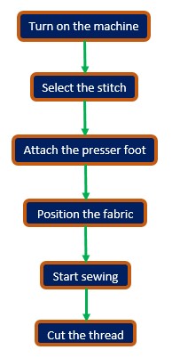
Experiment Name: Study on bar tack sewing machine with thread path diagram and sample production.
Introduction:
Industrial bar tack machine is actually a lockstitch machine group. By this machine, a very high density lockstitch is produced in very short length for increase the strength of that particular place. These machines are used for sewing both woven and knitted garments. For light thickness fabrics, needle size should be lower and heavy thickness fabric, height needle size should be used.
Objectives:
To know about bar tacking machine.
To know about different parts of the machine.
To know about the thread path of the machine.
To know about the specification of the machine.
To know about the adjustment points of the machine.
To know about working principle of the machine.
Bar Tack Sewing Machine Specification:
Main parts of Bar Tack Sewing Machine:
1. Thread stand and Cone case 9. Needle past box
2. Thread guide 10. Throat plate
3. Spring tensioner 11. Feed dog
4. Thread take-up lever 12. Stitch density regulator
5. Needle 13. Back stitch lever
6. Needle bar 14. Presser foot lever
7. Presser foot bar 15. Bobbin & bobbin case
8. Presser foot 16. Motor

Cone Holder: Supports the cone.
Stitch Description:
Stitch class: 300, Group: lock stitch type. In this machine there is two source of thread one is needle thread, another is bobbin thread. By interlacement of this two thread stitch is formed. Bobbin thread is stored in a bobbin which is placed under the needle bed of the machine. The needle of this machine moves a little front and back to form the stitch in a limited length of stitch in a heavy dense stitch to increase the seam strength on that point.
Working principle of Bar Tack Sewing Machine :
At first, this machine produces tack stitches in a small length (1-2 cm) and then sews covering stitches over and at right angles to the first stitches. The variables are the number of tacking stitches and the number of covering stitches. Typical uses are closing the ends of buttonholes, reinforcing the ends of pocket openings and the bottoms of flies and sewing on belt loops. The adjustment points of this machine are needle, pressure feed, stitch length, stitch density.
Uses of Bar Tracking Machine in Apparel Sewing:
Bar Tracking Sewing Machine is used to secure pocket corners, belt loops, the open end of a button hole, zipper flies.
Bar Tracking Sewing Machine is also used for small decorative tracks and shapes.
Conclusion:
Bar tack machine is one of the most important and most expensive machine of garments production. By this experiment, we have learnt about different parts and their function in garments of the bar tack machine. It’s different function in garments processing which would help us in our practical job life.
(15)
(0)
Type : pdf
Size : 115 mb
Page : 253
An introduction to quality control for the apparel industry by Pradip V Meht
Technology of Clothing Manufacture Revised by David J. Tyler Free download
Sewing Machine
A sewing machine is a textile machine used to stitch fabric, paper, card and other material together with thread. It is an important part of the garment manufacturing industry as well.
Innovation History of Sewing Machine
The Invention of the Sewing machine was the combined ideas and work of many inventors. In 1790, Thomas Saint, an Englishman, took out a patent on a machine for “quilting, stitching, and sewing, and for making shoes, and other articles. Saint’s machine can made only chain stitch.
In 1832, Walter Hunt developed a machine in his shop in New York City. He incorporated two new ideas i.e. eye-pointed needle and a locking stitch. Many other people contributed to the development of the sewing machine. In 1845, Elias Howe, an apprentice watchmaker from Boston, made a sewing machine that had a curved eye-pointed needle and an under-thread shuttle. This machine could sew 250 stitches per minute. That was five times as fast as the fastest hand sewer. In 1846, Isacc M. Singer, an American, produced a machine that had a straight needle and could sew continuously.
Different Parts of a Sewing Machine and Their Function
They are different types of sewing machines that are available in the market. The basic functionality of the machine is one and the same.
How a Sewing Machine Work?
General Sewing Procedure
Follow the basic procedures below to sew.
(0)
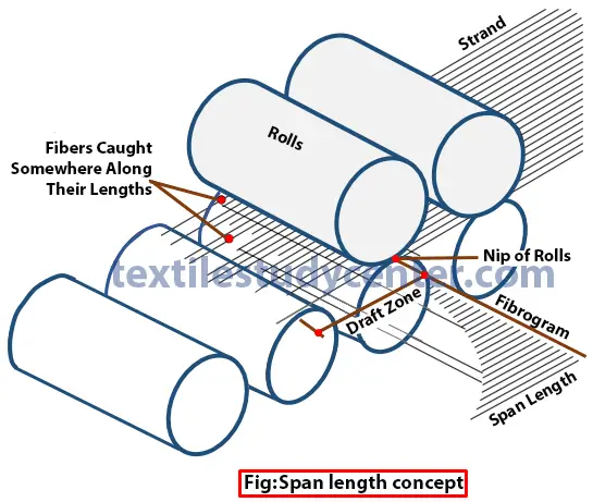
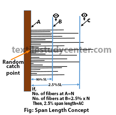
Span Length:
Span length is the distance exceeded by a stated percentage of fibers from a random catch point in drafting zone. 2.5% and 50% span length are the most commonly used by industry.
2.5% Span Length and 50% Span Length:
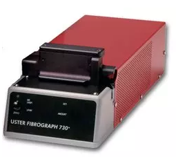
x % Span length is the distance spanned by x %of fibers in the specimen being tested when the fibers are parallelized and randomly distributed and where the initial starting point of the scanning in the test is considered 100%. This length is measured using “Digital Fibrograph‘.
Significance of 2.5% Span Length-
American dept. of agriculture shows that 2.5% span length best matches with the staple length assessed by the classer and hence 2.5%span has become a universal standard for evaluating cotton.
2.5% staple length is suitable for the spinning process.
The South India Textile Research Association (SITRA) gives the following empirical relationships to estimate the Effective Length and Mean Length from the Span lengths.
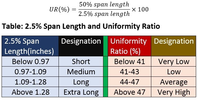
Uniformity Ratio:
The ratio between 50% span length and 2.5% span length is called uniformity ratio, express as a percentage.
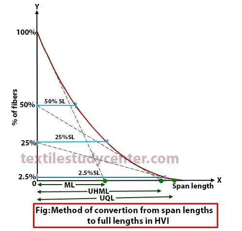
Estimation full length from span length:
In the High Volume Fiber Tester, full length obtained from the span length distribution by constructing tangents on the Fibrogram. The tangent to the Fibrograph drawn from the 100% point of fibers and extrapolating to the lengths axis indicates the Mean length (ML). Similarly drawing a tangent from the 50% point of fibers and extrapolating to the lengths axis indicates the Upper Half Mean length (UHML).
Floating Fiber Index (FFI):
Fibers in the drafting zone that are not clamped by either of the pairs of rollers of drafting zone are referred to as floating fiber index. It is expressed as a percentage and calculated by the following equation.
Short Fiber Content (SFC):
SFC can be calculated from the output of the fibrogram
SFC% = 50.01− 0.766×2.5%SL − 81.48× 50%SL
(0)
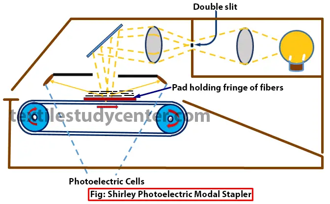
The original idea of the photoelectric scanning or Fibrograph method has been developed by Hertel in 1940 for testing cotton lint. This test method is much faster than the array method and is used widely in fiber laboratories for measuring fiber length and length distribution. These tests are performed with a Fibrograph instrument, which is a photoelectric device (fig.).
In Fibrograph, fiber samples are presented in the form of a pair of carefully prepared fringes. The light transmitted through these fringes is monitored by photoelectric current. The amount of light passing through the fiber sample is linearly proportional to the number of fibers in the light path. The changes in the photoelectric current are recorded graphically in the form of a Fibrogram as shown in Fig. From this Fibrogram various length parameters of practical interest, such as span length, mean length (OM), upper-half mean length (OR) and index of uniformity, given as the ratio of OM to OR, can be analyzed.
Preparation of Test Specimen
Test specimen can be prepared from the laboratory sample by on of the following method.
1) Hand Combing Method
Pick up a handful of cotton from the laboratory sample and separate it into two parts by pulling so as to expose a fresh surface of projecting fibers. Holding one of the hand combs in one hand and the opened lump of cotton in the other, transfer some of the projecting fibers on to the comb. Pick fresh lumps of cotton, and proceed in the same manner so that a pair of combs is filled with sufficient quantity of fibers drawn from 8 to 10 randomly picked lumps. Hold one comb in each hand, and untangle and parallelize the projecting fibers by mutual combing. The pair of combed beards constitutes the test specimen.
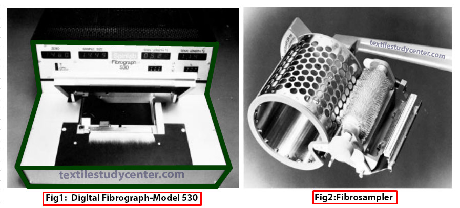
2) Fibro-Sampler Method
Mount one of the fibro-sample combs in the comb holder of the Fibro sampler, with the teeth uppermost. Place the laboratory sample in the cage and press it against the perforated surface. Maintain the pressure and rotate the sample holder round the drum counter-clockwise through 360°. Remove the loaded comb from the holder. Turn the sample in the cage to expose a fresh surface, and mount fibers in one more comb. Either one or a pair of combed beards constitute the test specimen depending upon the model of the instrument being used.
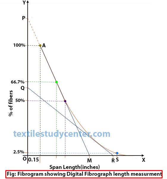
Fibrogram:
Fibrogram is an arrangement of fibers from shortest to longest in terms of span lengths. Fibrogram test are required for determining the length uniformity of fibers in the sample of cotton.
At any instant in time, fibers caught by the roller nips will depend on the randomness of their overlapping lengths; therefore, not all the length of a given fiber projects into draft zone. The lengths that project into the draft zone are called the span lengths, and the cumulative frequency distribution of the span length gives the Fibrogram.
Digital Fibrograph:
The digital fibrograph gives the tests results in digits or numerical form. Suppose In the 2.5% span the length is 1.14 inch while in the 50 percent span the length is 0.52 inch. The uniformity ratio is 46%.
Fibro sampler is used in later models to clamp the fibers on the comb. Fiber sample is put inside the cylinder of sampler. Fiber comb, with 13 needles/inch, is rotated around the fibro sampler, with pressure applied on the cotton, during which it picks up fibers projecting from the holes of sampler. The instrument is consequently insensitive to the presence of very short fibres, and in practice the Fibrogram has its origin at a point representing a length of 0.15 inch (3.8 mm).
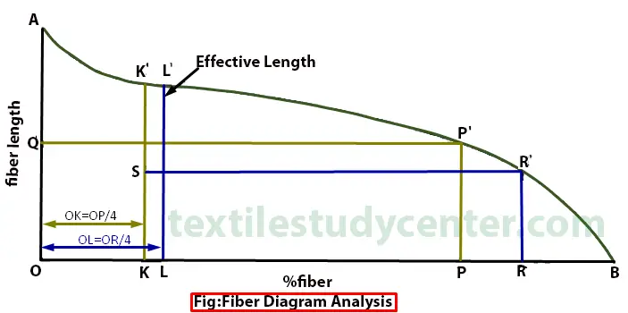
Digital Fibrogram may be analyzed graphically to yield various length parameters of interest to the producers and users of cotton. The tangent to the curve at its starting point A cuts OY at P and OX at M. Then OM is the mean length of the fibers in the original population longer than 0.15 inch (3.8 mm). If OP is bisected at Q and the tangent to the curve from Q cuts OX at R, then OR is the upper-half mean length, UHML, and the ratio of OM to OR is a valid index of uniformity.
(0)
Definition of length is based on two criteria- one based on its ‘full length’ i.e. end to end lengths (staple length, ML, EL, UHML,UQL) and the other based on ‘span length’(2.5% span length,50% span length, ML & UHML).
Mean length:
It is the arithmetic mean of the length of all the fibers present in a sample of the cotton. It can be calculated by number or weight of fibers.
Let us consider three fibers length (mm) and weight are l1,l2,l3 and w1,w2,w3 respectively.
Upper Half Mean Length (UHML):
UHML is the mean length by the number of fibers in the largest half by weight of fibers in a cotton sample, usually measured from the fibrogram. Upper half mean length is normally equivalent to the staple length.
Uniformity Index (UI):
The ratio between mean length (ML) & Upper half quartile length is called uniformity index, express as a percentage.
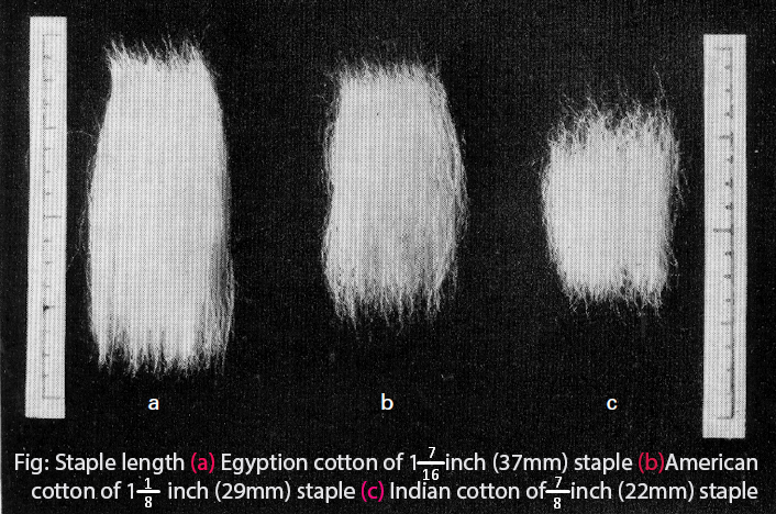
Staple length:
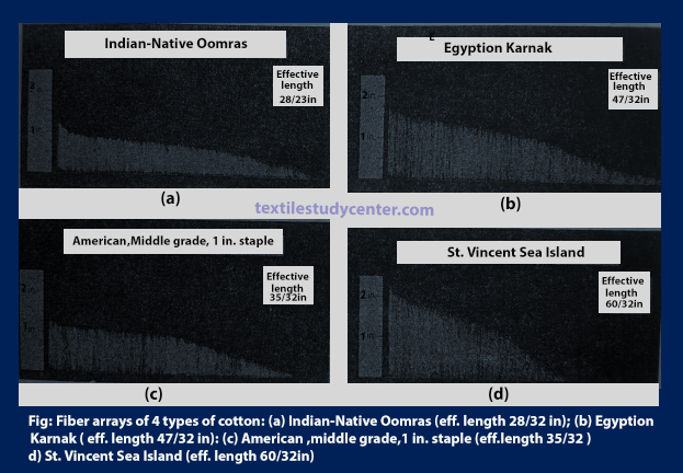
The most frequent length in a fibrous sample is called staple length. Staple length is one of the most important factors of cotton quality because both fiber fineness and fiber tensile strength are associated with staple length. The longer staples are usually finer and stronger than the shorter staples.
Staple length can be of following types:
Staple diagram:
Graphical representation of the end aligned fiber beard (arrangement of fibers by the length in decreasing order starting from a horizontal line) is called staple diagram.
Cumulative frequency fiber length distribution (CFD) is also called the staple diagram (in short staple spinning) or diagram of Hauteur (worsted spinning). It is produced by sorting, either by number or by weight, the straightened lengths of the individual fibers making the sample. Generally, the CFD is obtained manually by the Suter-Webb method.
Coefficient of fiber length variation (CV %):
The coefficient of variation of fiber length CV % is the ratio of σ divided by the mean length ML. Where σ is the standard deviation of fiber length.
Modal Length:
Modal length is the length in a fiber length frequency diagram, which has the highest frequency of occurrence. The modal length for long staple cotton is more than the mean length because of the progressive increase in the skewness of the fiber length distribution with increasing staple length.
Calculation of fiber length (on the basis of number & weight) from staple diagram
a) Mean Length (ML):
b) Upper Quartile Length (UQL):
UQL is the value of length for which 75% of all the observed values are lower, and 25% higher in the fiber sample.
c) Short Fiber Content (SFC):
SFC is the percentage by number or weight of fibers less than a specified length, 0.5 inches (12.7mm) for cotton, typically 25 or 40mm for wool.
(0)
As single fiber measurement takes time and hand stapling requires experience, alternative methods have been developed. There are two methods for laboratory analysis used to measure fiber length.
Fiber sorter method:
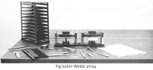
The fiber sorter is an instrument which enables the sample to be fractionalized into length groups. The Baer sorter, the Shirley comb sorter, and the Suter-Webb sorter are the most popular method of the fiber sorter. Basically, the operation involves four main steps:
Suter-Webb array (SW):
This method consists of a bed of upright and parallel combs which control the fibers and arranged it in the form of an array of uniform density in the descending order of length. In this way enable the sample (fibers) to be fractionated into length groups for determining cumulative fiber length distribution by weight in parameters upper quartile length (UQL), mean length (ML) and % short fibers (SFC) as illustrated in Fig. and dispersion percentage which is expressed as (CV%). The disadvantages of this device are time-consuming (2 hrs. per sample) and calls for considerable operator skill in sampling and preparing the diagram (Fig.).
The Shirley comb sorter Method
Principle
A sample of fibers is arranged in the form of an array in the descending order of length, and from a tracing of this array some fiber length parameters are calculated.
Apparatus
a) Two set of combs
b) Fiber grip
c) Teasing needle
d) Aluminum depressor
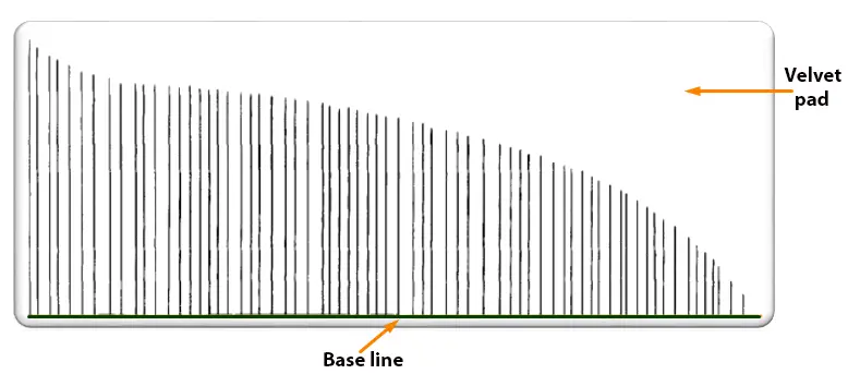
e) Velvet pad, and
f) Rectangular perspex scale (160 x 80 mm) marked in 5 mm squares.
Construction:
1) This instrument consists of a two set of combs (top & bottom) arranged at fixed intervals to hold the fibers and keep them straight.
2) Here 8 top combs and 9 bottom combs are used, each comb are spaced 6 mm (¼ inch) apart except the first two bottom comb which is 3/16 inch apart.
3) The distance from a row of bottom needles to a row of top needles is 3mm (1/8 inch).
4) An aluminum depressor, grip, teasing needles, velvet pad etc. are also used.
Procedure:
(0)