Wednesday, September 2, 2015

Fashion History


 Fashion History  


 What is Fashion??

        Fashion is the term used to describe a style of clothing or any other products worn or used by most people of a country. A fashion remains popular for a few months or years before being replaced by yet another fashion.

     Many writer, novelist, designer said about fashion describe as below:

           “We live not according to reason, but according to fashion”. 

                                                           Seneca, philosopher,  mid-1st century AD 

        “There’s never a new fashion but it’s old”

                                                           Geoffrey Chaucer, English poet  1340-1400

       “Fashion is not something that exists in dresses only. Fashion is in the sky, in the                          street,fashion has to do with ideas, the way we live, what is happening”

                                                           Coco Chanel, French fashion designer  1883-1971 

       “Fashion is a form of ugliness so intolerable that we have to alter it every six months”

                                                           Oscar Wilde, poet, novelist, dramatist and critic  1854-1900      

       “Fashion is like a fruit, you couldn’t eat it a day before and you can’t eat it a day after,                 its just about today”.

                                                                              Alber Elbaz , Israeli fashion designer 1961

       “Fashions fade, style is eternal”

                                                           Yves Saint Laurent, French fashion designer  1936-2008 

       “I don’t design clothes. I design dreams”

                                                           Ralph Lauren, American fashion designer 1939 


   Where are the world’s fashion centers?

 New York, Paris and Milan these cities are the major center for designers and manufacturers of fashion apparel and accessories.

London, Los Angeles, Toronto, Hong Kong, Sydney and Sao Paolo and many of other smaller market areas are organize to excellent designers and manufacturers to show the world upcoming something new.


 Areas of Fashion Analysis


      1. Architecture, interior design, landscape design

      2. Arts and crafts

     3. Body type, clothing or costume, cosmetics

     4. Dance and Music

     5. Forms of addressing and speech

     6. Economics and spending choices

     7. Entertainment, games, hobbies, sports

     8. Etiquette ( manner/custom )

     9. Management styles and ways of organizing

     10. Politics and media

     11. Philosophy and Spirituality

     12. Social networks

     13. Technology


Fashion Design 

        A range or line may be used to describe a more specific grouping of garments or products that are aligned to a commercial sales or marketing plan. This might be a category of garments such as a range of skirts,which would be merchandised across a defined color palette and fabric story or a group line, which would include items that could be merchandised and sold together as a group. Ranges and lines are interchangeable terms in Fashion Design


Fashion Design is generally considered to have started in the 19th century with Charles Frederick Worth who was the 1st person to sew their label into garments that they created. 


Fashion is About Designers


The main roles played by designers are: 

Creation

 Product development

 Communication


 Why people Started wearing clothes, Necessity of clothing


       1. To cover up their body

     2. To protect body from extreme weather situation as rain, strong sunlight, extreme heat or cold etc

     3. To protect them from any hazardous environment as fire, explosion, toxic or weapon etc

     4. To feel comfortable

     5. To make different from other society

     6. To beautify themselves

     7. Designation of Status

     8. Designation of Gender Differences

     9. Designation of Age

     10. For religious and cultural purpose

     11. Ceremonial use of clothing

     12. Clothing as an Art form

     13. Clothing as a means of Social Communication


Fashion History

Speed Frame and it's Function


                     Speed Frame and it’s Function


 Speed Frame/Roving Frame/Simplex machine

The output from the draw frame is fed into the roving frame (also called ‘speed frame or simplex machine or flyer frame‘) where the linear density of sliver is reduced by drafting and the resultant product is called the roving. After the drafting operation, the roving is wound on the bobbin. During winding, a little amount of twist is imparted to the roving.

Speed Frame

 Objects:

 To draft the drawframe sliver to reduce weight per unit length.

 To insert small amount of twist into the roving.

 To wind twisted roving onto the bobbin.

 Significant of Roving Frame/Why the Draw Sliver is not Direct Used in Ring Machine?

There are two principle region:

The first reason is related to the required draft. The draw sliver is to thick, untwist strand that tends to be hairy and to create fly. The draft needed to convert this to a yarn is in the resign of 300-500.The speed frame process minimizes the sliver weight to a suitable size for spinning into yarn and inserting twist, which maintains the integrity I the draft strands. It is impossible to feed the sliver to ring frame for yarn production due to limitation in draft in ring frame. So the fine twisted roving is better to this purpose.

The second reason is related with transportation and space limitation on ring frame. The draw frame can represent the worst conceivable mode of transport and presentation of feed material to the ring spinning frame.

 Tasks of Speed Frame/Functions of Speed Frame

The major tasks of the speed frame process are listed as follow

Creeling: To feed the sliver by the help of several rows of driven rollers to the machine.

Drafting: to reduce the size of the strand

Twisting: to impart necessary strength

Laying: to put the coils on the bobbins

Winding: to wind successive layers on the bobbin at the proper rate of speed

Building: to shorten successive layers to make conical ends on the package of roving

Doffing: To replace an empty bobbin at the place of full bobbin.

The twisted -roving system

Creeling:

 Creel is the place situated at the back of the machine where the raw material is placed to be fed to the drafting zone.

 Optimum creel tension draft should be selected to control sagging or stretch in drawing sliver.

Drafting:

 Drafting is normally carried out by a draft system with double apron capable of working with entering sliver counts of 0.12-024 Ne and counts of the delivered roving of 0.27—3 Ne.

 The draft given in the roving process will be in the range between 4 and 20 and can work fibers of a length of up to 60 mm.

Twisting:

 It is very important factor which produces strength in the roving and twist is inserted with the help of flyer.

 When flyer rotates, the twist is produce in the sliver.

 Twist level depends upon flyer speed and delivery speed.

Laying:

 Lay refers to the arrangement of the roving coils wound around the bobbin in any given layer. The closeness of the lay is measured in “coils per inch,” which means the number of roving coils wound around the bobbin per inch parallel to the axis of the bobbin.

 The purpose of the laying operation is to put the successive coils of roving side by side in a uniformly spaced arrangement.

 This regular, uniform arrangement is achieved by making the bobbins move up and down at a uniform rate of speed for each layer.

Winding:

 Winding is the process by means of which the roving is drawn from the front roll through the flyer and onto the bobbin.

 The rate of winding compared to the rate of delivery at the front roll controls the winding tension. 

Building:

 The building motion is controlled by the steady upward and downward movements of the bobbin rail containing the bobbins and spindles.

Doffing:

 It is the optional function of speed frame. Doffing could be done manually or automatically.


Speed Frame and it's Function

Machine Components of Speed Frame


Machine Components of Speed Frame

The important parts of speed frame are given as follows:

Bottom rollers

Rubber-covered top rollers

Top arm

Aprons (top and bottom)

Spacer

Condenser (inlet and floating)

Top arm

Flyer

Spindle

Pressure arm

 Top Rollers

 Top rollers are held strictly parallel to and in perfect alignment with bottom rollers.

 Top rollers covered with rubber cots play a significant role in the control of drafting irregularities.

 The hardness of top rollers is between 80° and 85° Shore, but the rollers over which the apron runs often have a hardness only slightly above 60° Shore. This permits better enclosure and guidance of the fiber strand during drafting.

 The top rollers must be pressed with relatively high force against the lower rollers to ensure guidance of the fibers. 100- 300 N per roller is normally applied depending on raw material and volume of fibers.

 The fiber or dust accumulation in the top roller neck should be cleaned frequently using picker gun.

Top Rollers

 Bottom Rollers

 Bottom rollers are made of steel

 The bottom rollers of speed frame exercise immense influence on the quality of roving.

 Precise concentricity of a bottom roller is a function of improved roving quality (evenness and strength).

 Bottom rollers having narrow tolerances of dimensions B, p, and T (Figure) produce fault-free roving.

 Eccentric or damaged bottom rollers, especially front bottom rollers, are the most common cause of unnecessary roving faults and excessive roller laps.

Bottom Rollers

 Top Arm

Spring loaded top arms are normally adopted in speed frame to get optimum pressure on top rollers to achieve required quality and performance. The top arm pressure and roller setting influence the roving quality and subsequently yarn quality.

Top Arm


 ApronsAprons

 Aprons are one of the most effective means to support the floating fibers and drastically reduce the drafting wave.  Apron wear is accelerated by high drafts and sliver linear density.

 It is essential that the aprons should extend as closely as possible to the nip line of the front rollers.

The top apron is short and made of synthetic rubber that has a thickness of about 1 mm. Bottom apron is larger and made of the same material as the upper one.
 Basically, synthetic aprons are made in an endless tubular form whereas leather aprons are made in open strips that are subsequently glued together to form an apron.

 The advantage of tubular construction is seamless and uniform along its circumference.

 The length of the aprons also called as the cradle length is kept approximately equal to the staple length of the fibers. The cradles for different staple length are shown in Figure.

Cradles for different staple length

 Cradle lengths according to the fiber length

   table1                    

 Spacer

The distance between top and bottom aprons is maintained by a small component called “cradle spacer” or “spacer,” which is inserted between the nose bar of the bottom apron and the cradle edge of top apron. The selection of spacer for a process depends on the hank of the sliver, break draft, and roving hank.

Cradle length and Cradle spacer

Spacer size of different roving hanks                                

Screenshot_1

Advantages and disadvantages of reducing the spacer size

table5

 Condenser

 Condensers placed in the drafting zone help to prevent the fiber strand from spreading apart during drafting.

 Condensers can be classified as feed (or inlet) condenser, middle condenser, and delivery (or floating)  condenser (Figure).

 Feed condenser is used just before the back pair of drafting rollers. The middle condenser is used near the nip of the middle pair of rollers and the third one is used just before the front pair of rollers.

 The main function of the feed condenser is to lead the sliver properly into the drafting arrangement.

 The main function of the last two guides is to bring back the fiber mass into a strand that tends to tear apart because of the drafting action.

 The size of condensers should be selected according to the volume of the fiber sliver (Table).


Find full post at  Machine Components of Speed Frame

Drafting System of Speed Frame II Draft Distribution of Speed Frame


Speed Frame Sections

A standard type of a speed frame has following sections:

Creel section

Drafting section

Twisting section

Winding section

 Creel section

 Creel is the place situated at the back of the machine where the raw material is placed to be fed to the drafting zone.

 The draw frame sliver cans are arranged in four or six rows in the creel zone.

 Since the fibers in the drawn sliver have less coherence so it is necessary to keep the surface speed of the guide rollers equal to the surface speed of the back drafting rollers so that any false drafting may be avoided that can damage the sliver.

 In modern fly frames, the creel transport rollers are arranged without vertical supporting rods, and these types of creels are called telescopic creels.

 Just before the drafting section a photo-electric stop motion is used which detects the presence of the sliver and as the sliver breaks it automatically stops the machine.

 Drafting section/Drafting system

The drafting section of the roving frame may be 3 over 3 or 4 over 4 with or without apron roller arrangement. Only the 3-over-3 or 4 over 4 roller with double apron drafting system are still to be found in modern machines offered by manufacturers. In general 3/3 drafting system is used, but for higher draft applications 4/4 drafting system is used. The draft often has limits not only at the upper limit (15 to 20), but also at lower limit. It is around 5 for cotton and 6 for synthetic fibers.

3-over-3 double apron drafting system:

3-over-3 double apron drafting system

In production of a roving, a 3-over-3 roller with double apron drafting system is commonly used to attenuate the sliver.

In a system of three pairs of rollers, there are two drafting zones. The first or back zone is designated the “break draft,” while the second or front zone is called the “main draft”.

A pair of endless aprons is positioned in the high-draft front zone and made to move at the surface speed of the middle-roller pair.

 As fibers enter the high-draft front zone, the aprons will hold them and assist in keeping them moving at the surface speed of the middle rollers, while preventing the short-fibers being dragged forward by those fibers nipped and accelerated by the front rollers.

 The magnitude of break draft is usually small, varying between 1.1 and 1.5; therefore the front draft (i.e. main draft) is responsible for the major part of the total attenuation desired.

  The total draft is defined as the ratio of the surface speed of the front rolls to the surface speed of the back rolls and is a product of the break draft and the main draft:

M1

4-over-4 double apron drafting system:

4-4 double apron drafting system

In 4-over-4 double apron drafting system, there are three drafting zones such as break draft, middle draft and front draft (or main draft).

Back draft is apply in back zone which affects roving evenness. Less amount of draft is apply in middle zone where the condenser is used to condense sheet like sliver. Maximum amount of draft is apply in front zone where the apron is used to move at the surface speed of the middle-roller pair.

The total draft is defined as the ratio of the surface speed of the front rolls to the surface speed of the back rolls and is a product of the break draft, middle draft and the main draft:

M2

 Draft distribution

An important consideration of the drafting zone is the draft distribution i.e. how much draft should be given in the back and front zones. In a 3-over-3 drafting system, there are two drafting zones such as break draft, and main draft. The first or back zone is designated the “break draft,” while the second or front zone is called the “main draft”. The total draft is the product of break and main draft. The break draft is in the range of 1.03 to 2.03 and all the remaining draft is given at the main drafting zone, generally ranging from about 5 to 18.

  Table: Recommended total draft range

table3

If the break draft is increased beyond an optimum value then the evenness of the spun yarn drastically reduces due to the formation of thick and thin places. It is recommended to keep the break draft as low as possible. The problems associated with the higher break draft than recommended are given as follows:

 Requires higher drafting forces that can create vibrations in the back zone of the drafting system. Break draft may have to be as low as 1.022 to prevent roller vibrations.

 Tends to create roving irregularities such as thick and thin places.

Table: Fiber and Machine Parameters Influencing Drafting Force

table4


Drafting System of Speed Frame II Draft Distribution of Speed Frame

Twisting and amounts of twist for different materials


Twisting section/Twisting and amounts of twist for different materials

The roving coming out of the front delivery roller is threaded through the top of the flyer, passes through its hollow leg around the presser arm on to the bobbin. The purpose of providing twist in roving is to give the strand sufficient strength to withstand the strain during unwinding in the creel of the ring frame. The insertion of twist is achieved by the rotation of the flyer. Twist level depends on flyer speed and delivery speed of the speed frame. The increase in twist reduces the productive capacity of the machine, so it is generally used in a range as limited as possible. The relationship between the twist and the aforementioned factors is given as follows:

M3

Since the rotary speed of the flyer is constant so the amount of twist inserted per unit length depends upon the delivery rate of the front delivery rollers.

Twist Insertion on Roving

False twisting devices are used on the flyers to add false twist when the roving is twisted between the front roller and the flyer. Because of this supplementary twist, the roving is strongly twisted, and this reduces the breakage rate. False twisting device is also called “twist crown.”

false twister

The level of twist imparted in the speed frame process varies with the staple of the cotton and the hank of the roving. Longer cotton requires less twist because individual fibers extend further in the strand and thus help to bind them together more securely than do short fibers. Finer roving requires more twist compared with coarser roving. The level of twist inserted for cotton at the roving frame is about 0.7 to 2 TPI. Higher twist in speed frame reduces the production rate and thus increases the cost of production. On the other hand very low twist makes the roving weak and it can break during the package winding.


Twisting and amounts of twist for different materials

Speed Frame Production Calculation


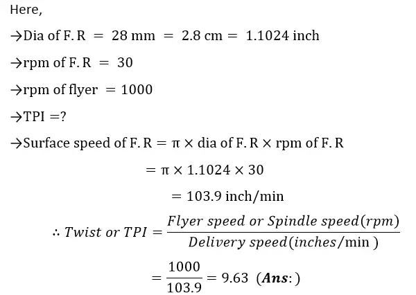
Math: Calculate the TPI (twist per inch) produced on a simplex with diameter of front roller 28 mm and its rpm be 30. The rpm of flyer is 1000.
Solution:
math1
Math: Calculate the TPI on simplex if the diameter of back roller is 15/16’’, rpm of B.R is 10, rpm of flyer is 1000 and draft is 6.
Solution:
math2
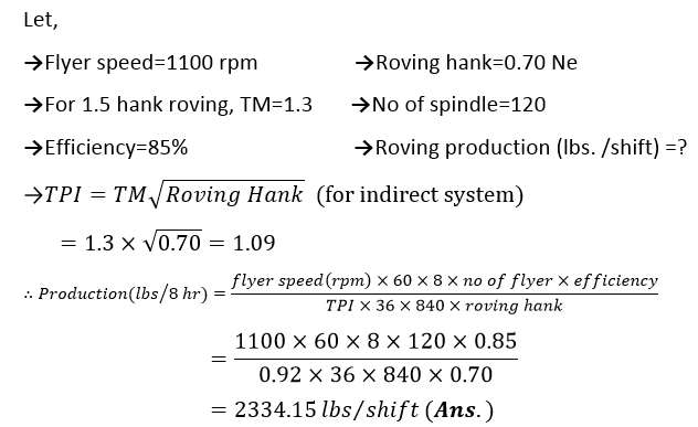
Math: Find out the production/shift in lbs. of a simplex machine. (Assume necessary parameters).
Solution:

math4
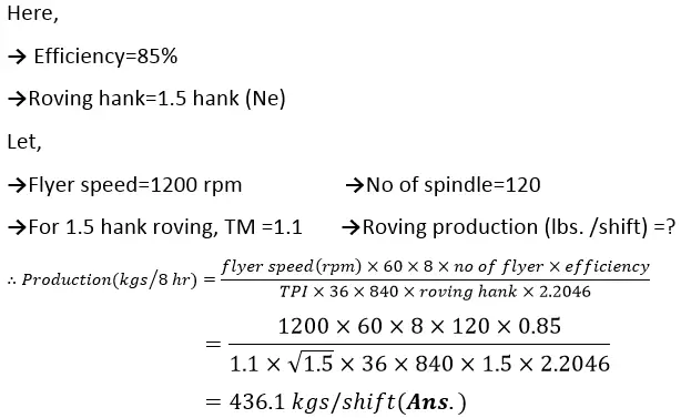
Math: Find out the production per shift of a modern speed frame at 85% efficiency to produce 1.5 hank roving. Assume necessary parameters.
Solution:
math5


Speed Frame Production Calculation